Circuit Potentiometer Wiper Arm Diagram
Digital potentiometer schematic compensation resistance initial position circuit wiper start simulate circuitlab created using Potentiometer wiper convert edn Potentiometer wiper positioned 15v r1 shown turn total range following
Position Sensors-The Potentiometer
Voltage calculate potentiometer range circuit divider resistance load change schematic variable output would parallel questions significance explain effect loading source Solved the potentiometer wiper is positioned at 25% of its How to connect a potentiometer in a circuit
Potentiometer resistor variable wiring mbed dependent clipartbest aaps vdr varistor potensiometer
Voltage regulatorPotentiometer position construction sensors sensor linear gif angular output resistive shaft signal Potentiometer_diagram – electronics goThe potentiometer: pinout, wiring, and how it works.
Potentiometer circuit amplifierSolved: calculate how the output voltage range would chang... Schematic exist potentiometers do circuitlab created usingPosition sensors-the potentiometer.

Convert voltage to potentiometer-wiper setting
Potentiometer constructionalPotentiometer wiring Potentiometer wiring wiper inside electronic resistance middle guide circuits build left move side when turningPotentiometer diagram, symbol, and construction.
Wiring diagram potentiometer .


Solved The potentiometer wiper is positioned at 25% of its | Chegg.com
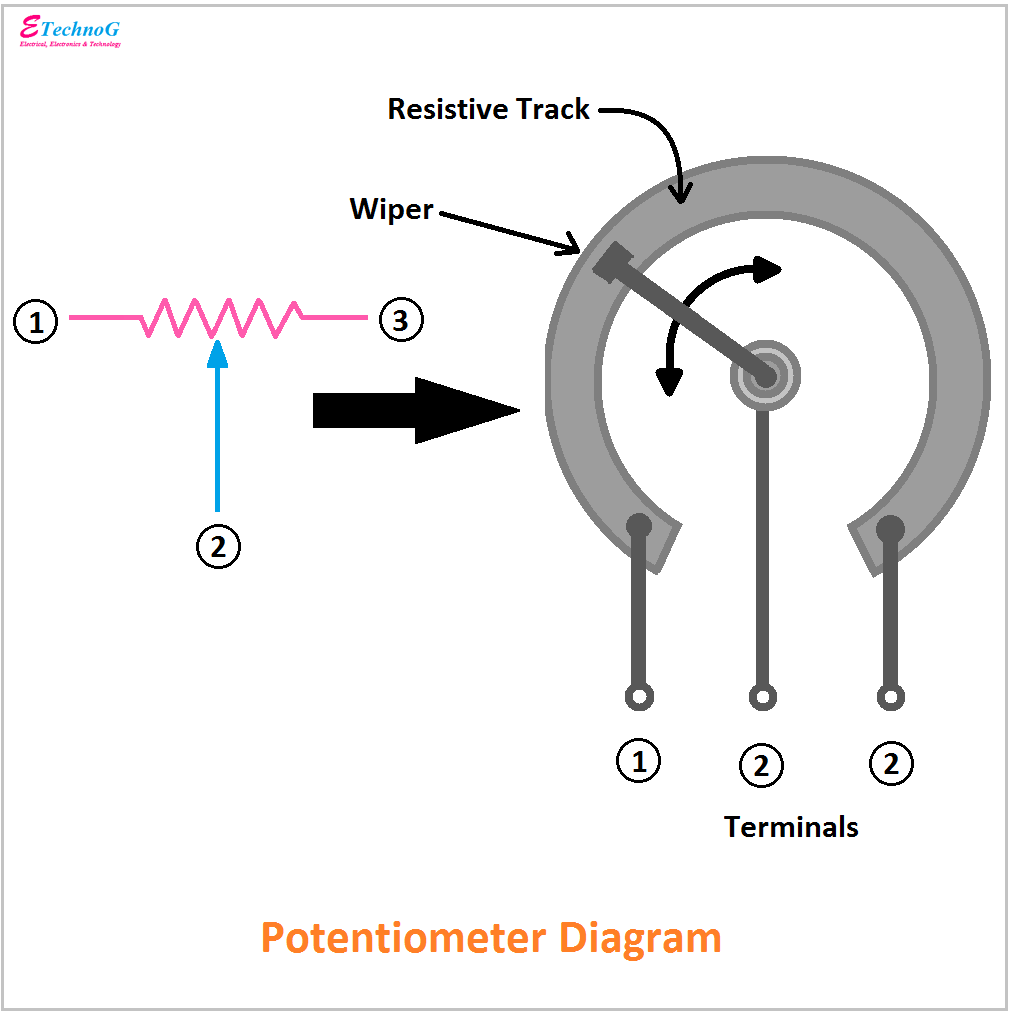
Potentiometer Diagram, Symbol, and Construction - ETechnoG

Solved: Calculate How The Output Voltage Range Would Chang... | Chegg.com

voltage regulator - Digital potentiometer, initial (wiper+start

Wiring Diagram Potentiometer - Wiring Diagram

Position Sensors-The Potentiometer

The Potentiometer: Pinout, Wiring, and How It Works

components - Do ‘wiperless’ potentiometers exist? - Electrical

potentiometer_diagram – Electronics Go